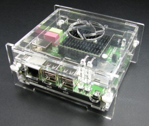
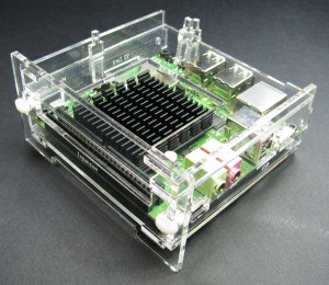
ODROID-X Enclosure with Fan Mount Assembly Instructions
Step 1: Prep the Parts
Before assembly you need to remove the paper mask from all the acrylic parts in the kit. It's useful to have fingernails or someone with fingernails that's willing to help for this step.
Step 2: Mount the Board
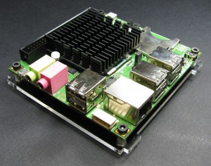
Using the M3x14 bolts and nylon standoffs in the kit, remove the rubber feet from the ODROID-X board and mount it to the bottom piece.
Step 3: Start Case Assembly
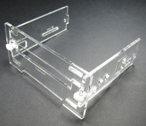
Clip the side with the audio jacks and the side with the SD card slot to the expansion side as shown (note that though the audio jacks aren't labeled correctly in these pics, they were corrected on the final design, my bad).
Step 4: Install the Bottom
Slide the bottom mount into the tabs on the case assembly you clipped together in the previous step.
Step 5: Install the Middle and Install Button Standoffs
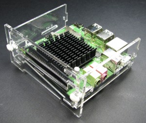
Next, slide the middle layer and install the button standoffs. It's a good idea to hold the bottom and middle layers in place (with the tabs securely seated into the expansion side) with one hand while installing the standoffs and when installing the top in the next step.
Step 6: Install the Top
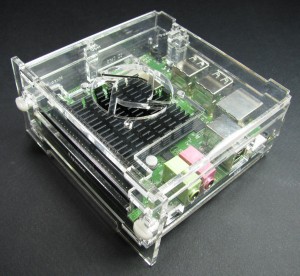
Next we install the top much like we did the bottom. The top should rest on the button standoffs as shown. If you want to install a fan in your enclosure, do so before installing the top. Skip down to the "Fan Prep and Installation" section for more details on installing the fan.
Step 7: Finish Assembly
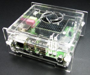
Place the Ethernet side and slide the clips into place to finish assembly.
Fan Prep and Installation
The fan I'm using here is Digikey part number . It's a 5 volt 40mm fan that's fairly quiet. I'm also using 0.1" and that I ordered from Digikey, but all these components should be available from other electronics suppliers as well.
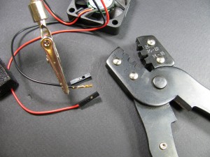
First off, you'll need to crimp the terminal connectors on to the lead wires of the fan. You may need to strip the end of the lead wires just a bit to get them the right length. Using the appropriate terminal crimp tool (pictured) will save you a lot of time and effort. You want the fingers on the end of terminal connector to wrap nicely around the insulation of the lead wire and have the exposed tinned wire of the clamped in place and making good contact with the connector (see pic). You can optionally add just a bit of solder to the very back of the connector just to ensure a good connection, but don't overdo it as solder can wick into the terminal connecter easily and interfere with its operation.
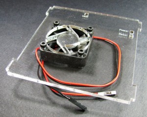
Next, we use some M3x16 bolts to attach the fan to the top of the case as shown. If you use the same fan that I did, make sure the fan guard fins are on the bottom so your fan will be blowing on to the heat sink.
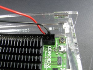
Next we'll need to connect the fan to power. Pin 50 of the expansion header is ground and pin 46 is connected to the 5V in from the power connector. You can use these pins to power your case fan as shown (GPIOs do not supply enough current to power the fan directly, but could with the help of some external circuitry). In this configuration your fan will always be on whenever external power is applied.
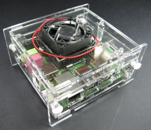
Now just wrap the power leads to the fan out of the way and install the top as you normally would and you've got active cooling!
